pantograph design calculation
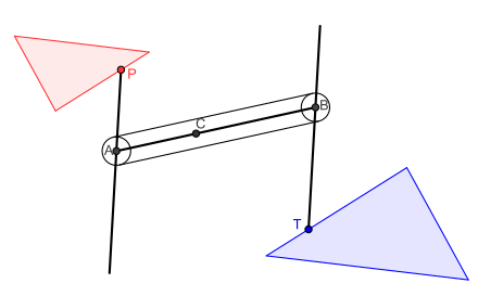
Four rods are jointed together to form a parallelogram the sides of which can be lengthened or shortened to suit the scale of reproduction. The aerodynamic forces of pantographs in high-speed operation were simulated numerically with the finite volume method on the basis of the three-dimensional steady incompressible N-S.

A Scissors Lift Uses Linked Folding Supports In A Crisscross X Pattern Known As A Pantograph The Extensi Scissor Lift Motorcycle Lift Table Scissor Jacks
Roll the machine down so its between the two dashed lines at the bottom of the pantograph design.
. The scale factor is the ratio. Typically a single or double wire is used with the return current running through the rails. The Pantograph Planner Calculator will tell you which Pantograph Planner template to use and which index mark to use for the information you provided.
Among them the X-axis represents the running time of pantographs head and Y-axis represents the running trajectory of pantographs head in the direction of the locomotive. This is now perfectly positioned on the dashed line that runs along the bottom of the pantograph design. DESIGN CALCULATION Design of Bars The design of the pantograph is based on the diagram and the scale of the enlarged o r reduced diagram.
Tour of the Pantograph Planner The Pantograph Planner legend tells you the spacing each index mark represents. In pantograph and overhead contact line system simulation pantographs are usually be seen as a mass-dumping-spring model as shown in Fig. The most important point part of this type of engraver is the construction of the square Parallelogram.
Discussion in Calculations started by Alex Katz Sep 25 2016. - Details of simple pantograph. Scale ratio Scale ratio Scale ratio.
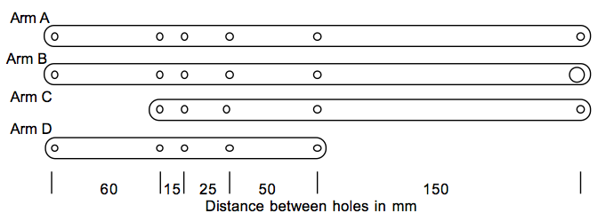
This document provides step by step instructions on how to use the Pantograph Planner. At this point I will present the design that is displayed in the Photograph The arms according to the drawing are 712 long from the center points of the two bushes the 12 stainless steel pipe is. The Pantograph Planner helps to free the quilter from the frustrations of positioning the rows for edge to edge quilting.
In rough calculation the stiffness is allowed to be 10 10 Nm. The main requirement for overhead line and pantograph monitoring are accurate measurements within a high-voltage environment 15 25 kVOptical sensors are passive elements and as their measurement principle is based on light no active excitation of the sensors is neededThat means that there are no interferences with. START position of the.
In a Python 3 shell create a PantoGraph instance using the values you noted earlier. Siemens Mobility performs the entire development process including design construction calculation simulation prototype building and production in Austria. Then as you tighten up the backing fabric and quilt top the quilt and machine will naturally move around 14-inch.
The formula used to find the scale ratio is. A pantograph is an apparatus mounted on the roof of an electric train tram or electric bus to collect power through contact with an overhead line. Click on the Compute button.
Because stiffness of force sensors is much larger than the one in pantograph mass model. The mechanics of the device serve to keep that ratio constant as the mechanism is rotated expanded andor contracted. Enter the quilt length the pattern width and the minimum amount of space you want between each row.
Distance from the fixed point to the drawing point distance from the fixed point to the tracing point. If you can build a prototype and test it to verify your design calculations it was built right - depending on how you test it you might also be able to validate your design purpose built. By simulation image the running trajectory of pantographs head is not a straight line.
By contrast battery electric buses and trains are charged at charging stations. The plank follows a straight-line path on the carpet surface. In this paper Hoekens and Pantograph mechanisms are used to obtain a straight-line path for.
Alex Katz New Member. The pantograph is a simple apparatus for copying drawings maps designs etc on a reduced or enlarged scale or to the same size as the original. A sketch of a pantograph is given in Fig.
Robust Accurate and Stable. Scissor lift Pantograph calculation. From pantograph import pg PantoGraph driver follower motor_1_pos motor_2_pos The servos and arms will move immediately this is why its important to have fastened the arms loosely.
If a motor is going to be used it needs to be a strong and balanced design. The pantograph is a common type of current collector. The specially developed hardware-in-the-loop test facility is unique in the world and makes it possible to emulate the interaction between the pantograph and simulated overhead.

Pantograph Model And Geometry Of The Frame Download Scientific Diagram

Scissor Lift Jack Equations And Loading Calculator Engineers Edge Scissor Lift Mechanical Engineering Design Scissors

Panto Graph Mechanism Design Grabcad Tutorials

Simulative Calculation And Optimal Design Of Scissor Lift Mechanism Humidor Woodworking Plans Welding Table Woodworking For Dummies

Pantograph Configuration Download Scientific Diagram

Pantograph Degrees Of Freedom Raising Of The Mechanism Up Left Download Scientific Diagram

A Pantograph Of Two Masses Frontal View And Detail Of The Contact Force Download Scientific Diagram

Peter S Articles How To Build A Pantograph

Panto Graph Mechanism Design Grabcad Tutorials

Panto Graph Mechanism Design Grabcad Tutorials

Graphical Representation Of A Pantograph Model A Two Dimensional Download Scientific Diagram

Pantograph Wikipedia Woodworking Wood Worker Woodworking Tips

Scissor Lifts Information On Globalspec Scissor Lift Metal Working Projects Lift Table
Design And Control Of A Pantograph Robot Northwestern Mechatronics Wiki


Comments
Post a Comment